Edit Array
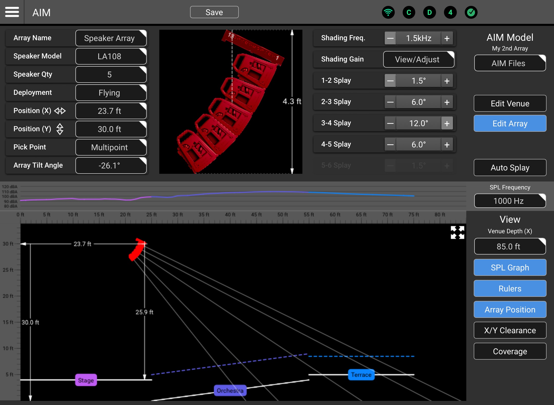
The Edit Array area of AIM![]() Array Installation Modeling (AIM) is a QSC System Navigator prediction tool used for visualization of array coverage in a scaled, graphical model of a venue or installation space. AIM also provides dimensional and weight data for an array as well as pick-point recommendations. is used to select an L Class loudspeaker model, specify the quantity of loudspeakers in the array and make deployment selections.
Array Installation Modeling (AIM) is a QSC System Navigator prediction tool used for visualization of array coverage in a scaled, graphical model of a venue or installation space. AIM also provides dimensional and weight data for an array as well as pick-point recommendations. is used to select an L Class loudspeaker model, specify the quantity of loudspeakers in the array and make deployment selections.
-
Array Name – Select the field to enter a name for the array.
-
Speaker Model – Touch/click to display a dropdown menu where AIM compatible loudspeakers may be selected.
-
Speaker Qty – Touch/click to display a dropdown menu where the quantity of loudspeakers may be specified.
-
Deployment – Touch/click to display a dropdown menu where deployment options may be selected.
-
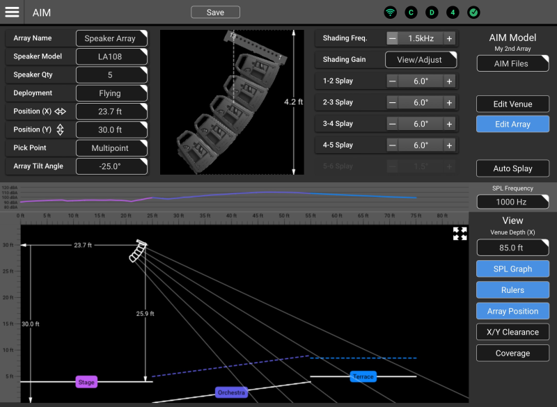
Flying (example shown above) – The array will be displayed with its array frame at the top.
-
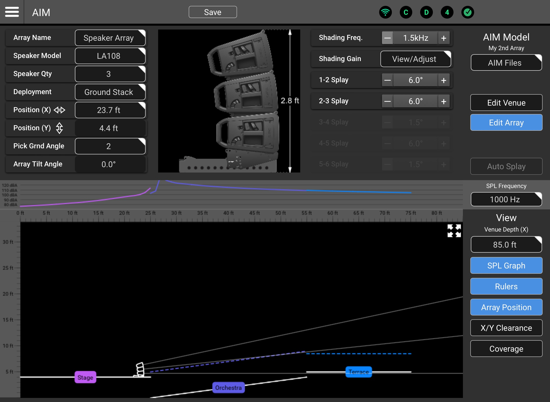
Ground Stack – The array will be displayed on top of the Array Frame (LA108-AF or LA112-AF) and Stack Adapter (LA108-KIT-SA or LA112-KIT-SA). The subwoofer(s) are not depicted in this SysNav version.
Note:
• Vertical position is limited to a maximum height above the supporting surface of 72 in / 1.8 m.
• The array size is limited to 4x LA108 or 3x LA112.
• The Stack Adapter supports array tilt angles of 6°, 0°, -6°, and -12°. Example: Ground stacked deployment
 -
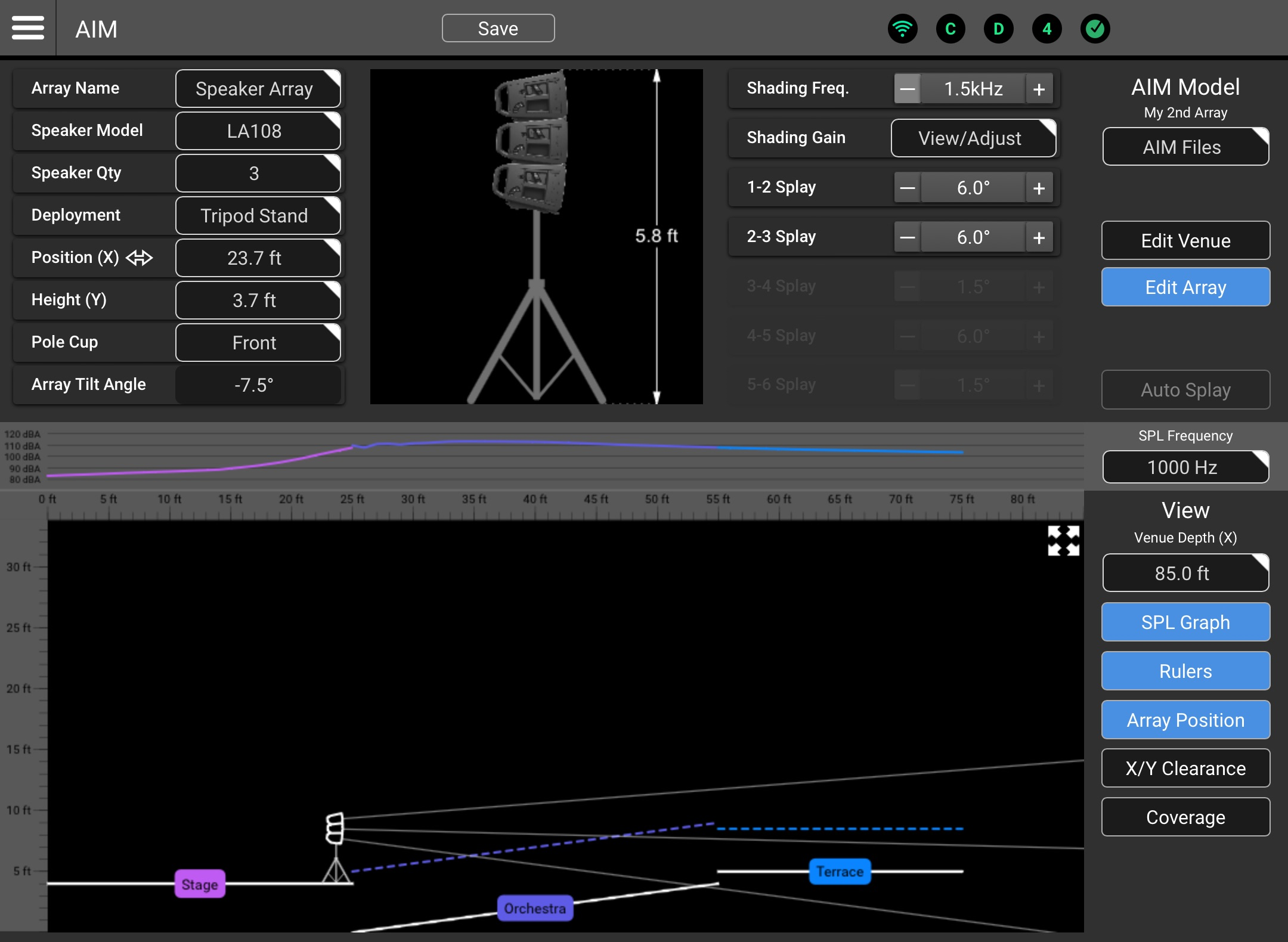
Tripod or Pole Mount – The array will be displayed on top of a pole that extends to the supporting surface. The subwoofer(s) or tripod are not depicted in this SysNav version.
Note:
• Vertical position is limited to a maximum height above the supporting surface of 90 in / 2.3 m).
• The array size is limited to 3x LA108 or 2x LA112.
• The loudspeaker’s dual pole sockets support array tilt angles of 0° and -7.5°. Example: Tripod or pole deployment
-
-
Position (X) – When the field is selected, the keypad may be used to input the horizontal distance from the origin point. The keypad nudge buttons may also be used to nudge the array.
Note: The array position may also be changed by dragging the array icon in the venue model.
-
Position (Y) – When the field is selected, the keypad may be used to input the vertical distance from the origin point. The keypad nudge buttons may also be used to nudge the array.
Note: The array position datum point will vary depending on deployment:
• Flying array – Middle of the upper edge of the topmost loudspeaker.
• Pole or speaker stand – Top of the pole cup.
• Ground stack – Lower front corner of the stack adapter. -
Pick Point
 When suspending a loudspeaker array, pick point refers to the point (or points) where the rigging hardware is attached to the array frame mounted at the top of the array. – This function is used to specify the tilt-angle for the array. Click the field to see the
  Pick Point dropdown menu:
-
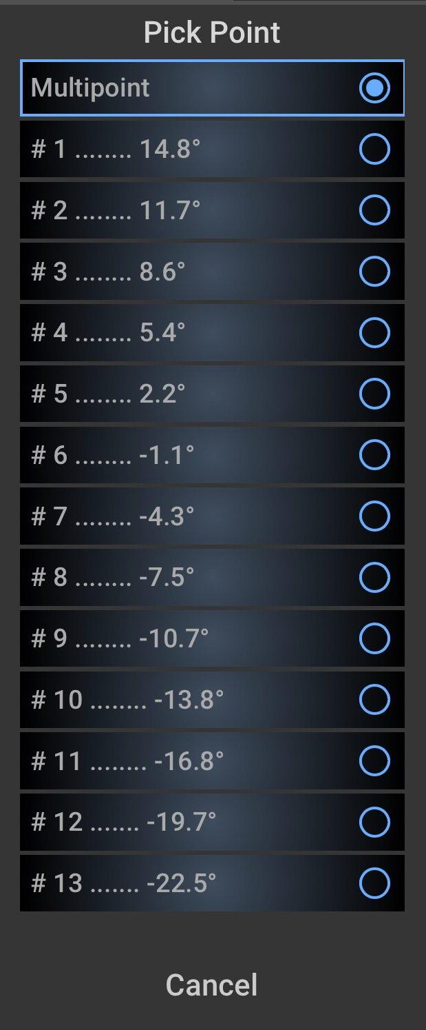
Multipoint – When this options is selected, the user may specify the desired tilt angle using the Array Tilt Angle field below.
-
#1 to #13 (single pick point) – The L Class array frame provides 13 attachment points. AIM calculates and displays a tilt angle based on the specified array configuration. If deployment using a single point of attachment is to be used, select the point that comes closest to providing the desired tilt angle. There are limitations to the tilt angles that can be achieved using a single pick point. For those applications a multipoint hang is required.
Note: In the real world, parameters such as the weight of electrical cabling or other suspension hardware can affect the tilt angle of a physical array using a single pick-point.
-
-
Array Tilt Angle – If the Pick Point selection is “Multipoint”, this field is used to input and/or indicate the array tilt angle. A tilt of 0° indicates that the fly-bar and the horizontal axis of the top loudspeaker in the array is parallel to the ground. A negative number indicates the array is tilted down.
Tip: The array tilt angle may also be adjusted by dragging the coverage pattern in the model.
-
Array Graphic (Upper Center) – Depicts a side view of the array in a flying, ground-stacked or tripod mounted deployment along with the Array Height and Center of Gravity (indicated by a vertical dotted line – flying arrays only).
-
Shading Freq. – Displays and selects the HF (High-Frequency) shading frequency for the array.
-
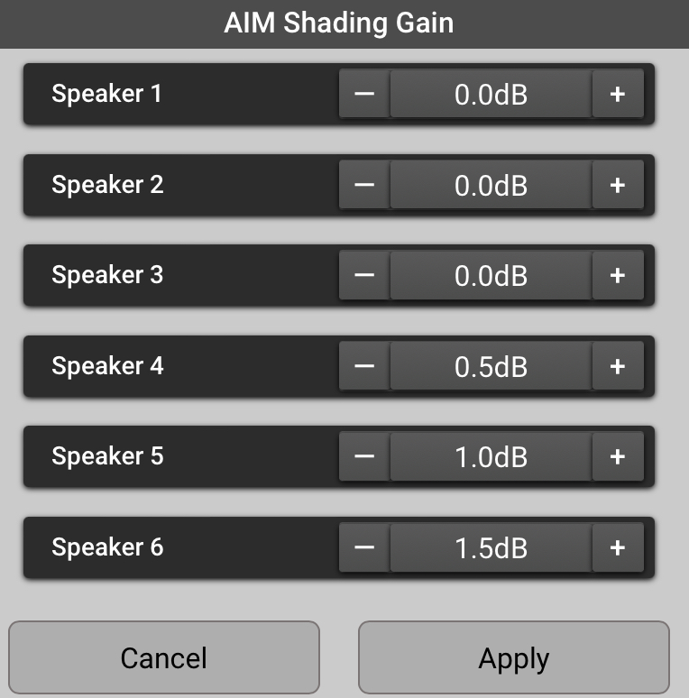
Shading Gain – Displays and adjusts the gain for the HF Shading
Generally, it is good practice to have the same signal processing parameters applied to all loudspeakers in an array. Array Shading is an exception. Array Shading is accomplished by adjusting the high-frequency output level of individual array loudspeakers relative to others in order to achieve a desired frequency balance across the listening area.. Example: Shading Gain Controls
 -
Splay
The angle between two adjacent loudspeakers in an array. – Clicking - or + adjusts the angle between two adjacent loudspeakers. (Note that the angle between the array frame and the topmost loudspeaker is not adjustable.)Note: Optimum deployment of an L Class loudspeaker array requires that each splay angle be equal to or greater than the splay angle above it. Any other deployment results in a “broken” or “convoluted” array. When an unsupported configuration is entered, the array loudspeakers will be displayed in red.
 Example: Unsupported configuration
Other Functions and Views
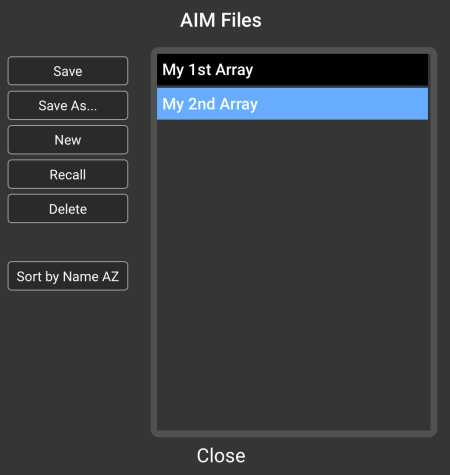
AIM Files
AIM Files may be stored, recalled and managed by touching or clicking the Aim Files button.
-
Save – Saves the most recently opened AIM model with any changes.
-
Save As… – Saves the current AIM model with a new name.
-
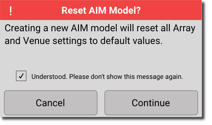
New – Creates a new AIM model with all parameters set to default and opens a naming dialog window. A popup window confirms the operation:

-
Recall – Opens the selected AIM model.
-
Delete – Clears the selected AIM model from memory.
-
Sort by Name – Sorts the AIM models in ascending or descending order.
-
Close – returns to the Edit Venue or Edit Array screen.
Auto Splay
The Auto Splay feature provides a recommendation for array tilt and splay angles based on the selected array and the audience areas that have been defined in the model.
Venue Model
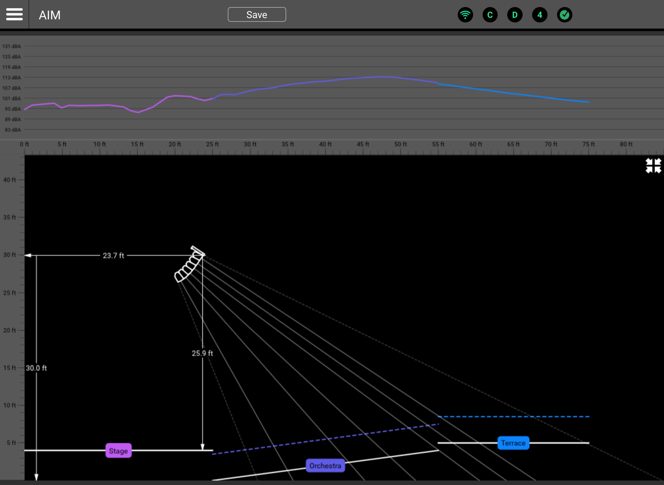
The Venue Model is displayed in Edit Venue as well as Edit Array modes.
-
SPL Graphic Display – Displays the predicted sound pressure level for the modeled venue and array. The color of the traces corresponds with the color of the corresponding area. The expand/collapse button (described below) provides a higher resolution display.
-
SPL Frequency – Selects the frequency used for the SPL calculation.
-
Array Position Icon – Depicts the position of the array in the model. The array may be dragged to change it’s location. The array’s on-axis “beams” may be dragged to adjust the Array Tilt Angel.
-
View Controls
-
Venue Depth – Adjusts the depth of the model. The feature allows the model to make best use of the window. The model will automatically resize to accommodate a vertical (Y) change to the array position.
-
SPL Graph – Conceals or reveals the SPL Graph.
-
Rulers – Conceals or reveals the horizontal and vertical venue rulers.
-
Array Position Callouts – Conceals or reveals the array position callouts in the model. These are indicated by solid white lines, and are used to indicate the horizontal and vertical distance from the model origin points to the array datum point, as well as the vertical distance from the array datum point to the surface of the area directly below the array.
-
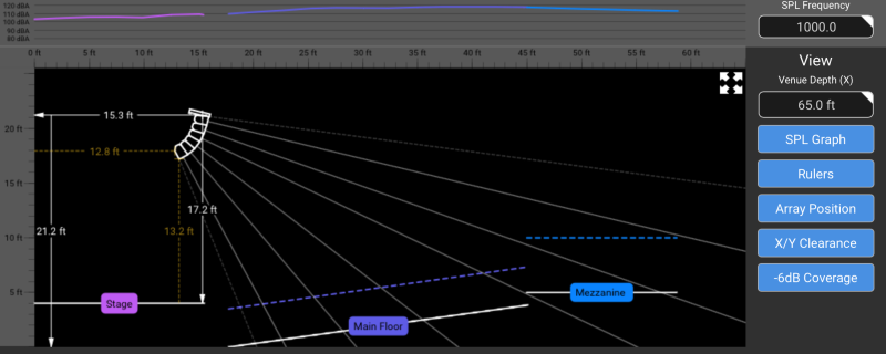
X/Y Clearance – Conceals or reveals the X/Y position call-outs in the model. These are represented by dashed yellow lines, and are used to indicate the distance between the rearmost point of the array and the leftmost point of the model, as well as the distance between the lowest point of the array and the surface of the area directly below the array.
-
Coverage – Reveals or conceals two dotted lines at the top and the bottom of the array coverage graphic. Referenced to the array on-axis coverage, these lines indicate the theoretical position in the vertical plane where the SPL has dropped by 6 dB for the top and lowest loudspeakers. These lines represent the nominal vertical coverage and will be positioned 7.5° off axis to the bottom and top-most array member loudspeakers.
-
-
Expand / Collapse – The Venue model, rulers, and SPL graph can be expanded to occupy the full width of the screen and display an SPL graph with a greater range and higher resolution.
 Example: Full-width view
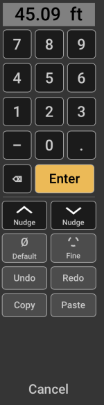
Keypad
The keypad is used for entry of numeric values. It appears whenever a value field is selected. The keyed-in value is entered into the AIM model when the Enter key is touched or clicked. If the device that’s running SysNav has a keyboard, it may also be used for numeric value entry. Other controls include:
|
|